In Analyzing A Series Rlc Circuit The Reference Is The
Breaking News Today
Mar 19, 2025 · 7 min read
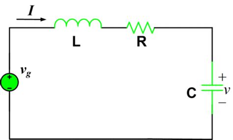
Table of Contents
In Analyzing a Series RLC Circuit, the Reference Is…
Analyzing a series RLC circuit requires a firm understanding of its components and their interaction. The key to unlocking its behavior lies in establishing a reference point, which dictates the direction of current flow and the polarity of voltages across each component. This seemingly simple choice profoundly impacts how we analyze the circuit's behavior, particularly in determining the phase relationships between voltage and current. Let's delve into the intricacies of RLC circuit analysis, focusing on the crucial role of the reference point.
Understanding the Components: R, L, and C
Before we discuss the reference point, let's briefly review the characteristics of the three primary components in a series RLC circuit:
Resistor (R)
The resistor is a passive component that opposes the flow of current. Its behavior is governed by Ohm's Law: V = IR, where V is the voltage across the resistor, I is the current flowing through it, and R is its resistance. The voltage across a resistor is in-phase with the current flowing through it.
Inductor (L)
The inductor is a passive component that stores energy in a magnetic field. Its behavior is defined by the equation: V = L(di/dt), where V is the voltage across the inductor, L is its inductance, and di/dt is the rate of change of current. The voltage across an inductor leads the current by 90 degrees. This means that the voltage reaches its peak value before the current.
Capacitor (C)
The capacitor is a passive component that stores energy in an electric field. Its behavior is described by: I = C(dV/dt), where I is the current flowing through the capacitor, C is its capacitance, and dV/dt is the rate of change of voltage. The current through a capacitor leads the voltage by 90 degrees. In other words, the current reaches its peak value before the voltage.
The Significance of the Reference Point
The choice of reference point in an RLC circuit determines the passive sign convention. This convention dictates the polarity of voltages and the direction of current flow. We typically choose a reference direction for the current flowing through the series circuit. Then, applying the passive sign convention, if the current flows into the positive terminal of a component, the voltage across that component is considered positive. Conversely, if the current flows out of the positive terminal, the voltage is considered negative.
This seemingly small detail significantly influences the signs in our equations and, subsequently, the results of our analysis, especially when dealing with phasor representations in AC circuits. Inconsistent application of the passive sign convention can lead to incorrect phase relationships and inaccurate calculations of impedance, resonant frequency, and other crucial circuit parameters.
Analyzing the Series RLC Circuit: Different Approaches
Several methods exist for analyzing a series RLC circuit. The choice depends on the specifics of the problem, such as whether the source is AC or DC, and the desired information (e.g., impedance, resonant frequency, current, voltage across each component).
1. Mesh Analysis (for AC and DC)
Mesh analysis is a powerful technique applicable to both AC and DC circuits. In a series RLC circuit, there's only one mesh, simplifying the process. We can write a single equation using Kirchhoff's Voltage Law (KVL), which states that the sum of voltages around a closed loop is zero. Remember to adhere strictly to the chosen reference direction and the passive sign convention when applying KVL.
For an AC circuit with a sinusoidal source, we'll typically use phasors to represent voltages and currents. This transforms the differential equations describing the circuit's behavior into algebraic equations, making the analysis significantly easier.
2. Nodal Analysis (less practical for series circuits)
While nodal analysis is a robust method for more complex circuits, it's less practical for simple series RLC circuits. This is because a series connection implies a single path for current flow, resulting in only one node where we can apply KCL (Kirchhoff's Current Law). Therefore, mesh analysis offers a more straightforward solution in this case.
3. Impedance Method (for AC circuits)
In AC circuits, the impedance method offers an elegant approach to analyze series RLC circuits. Impedance (Z) represents the total opposition to current flow, encompassing resistance, inductive reactance (XL = 2πfL), and capacitive reactance (XC = 1/(2πfC)). The total impedance of a series RLC circuit is:
Z = R + j(XL - XC)
where 'j' is the imaginary unit (√-1). Ohm's Law can be applied using impedance: V = IZ, where V and I are the phasor representations of voltage and current, respectively. The phase angle of the impedance determines the phase relationship between voltage and current.
4. Time-Domain Analysis (for transient response)
When considering the transient response of a series RLC circuit (how the current and voltages change over time after a sudden change in the source), we use differential equations. This approach directly solves for the time-dependent behavior of the circuit variables. This analysis often involves solving second-order differential equations, which require a good understanding of calculus and differential equations. The solutions often involve exponential terms, reflecting the natural decay or growth of the current and voltage. The damping factor plays a crucial role determining if the response is overdamped, critically damped, or underdamped. This heavily depends on the values of R, L, and C.
Resonance in Series RLC Circuits
A particularly important phenomenon in series RLC circuits is resonance. Resonance occurs when the inductive reactance (XL) and capacitive reactance (XC) are equal:
XL = XC
This leads to a condition where the total impedance (Z) is purely resistive (Z = R), resulting in a maximum current for a given voltage. The resonant frequency (fr) at which this occurs is:
fr = 1/(2π√(LC))
At resonance, the voltage across the inductor and capacitor can be significantly larger than the source voltage, a phenomenon called voltage magnification. Understanding resonance is crucial in many applications, including tuning circuits in radio receivers and filters in signal processing.
Practical Applications of Series RLC Circuits
Series RLC circuits are fundamental building blocks in numerous electronic systems. Their applications span various domains:
-
Tuning Circuits: In radio receivers, a series RLC circuit is used to select a specific frequency from a range of frequencies received by the antenna. By adjusting the capacitance or inductance, the resonant frequency can be tuned to match the desired radio station frequency.
-
Filters: Series RLC circuits can act as filters, selectively allowing certain frequencies to pass while attenuating others. Band-pass filters, for instance, allow a narrow range of frequencies to pass, while band-stop filters suppress a specific frequency range.
-
Oscillators: With proper design, a series RLC circuit can be incorporated into oscillator circuits to generate sinusoidal signals at a specific frequency.
-
Power Supply Filters: Series RLC circuits can be employed to filter out unwanted noise and ripple in power supplies, producing a smoother, cleaner DC voltage.
-
Impedance Matching: In some applications, an RLC circuit can act as an impedance matching network, ensuring efficient power transfer between different parts of a system.
Conclusion
Analyzing a series RLC circuit requires a meticulous approach, emphasizing the correct application of the passive sign convention based on the chosen reference point. Choosing a consistent reference point ensures accuracy in applying methods such as mesh analysis, impedance analysis, and time-domain analysis. Understanding the behavior of each component (resistor, inductor, capacitor) and their interplay is crucial for comprehending the overall circuit response, including resonance phenomena and transient behavior. The versatile nature of series RLC circuits makes them essential components in countless electronic systems, solidifying their place as a cornerstone of electrical engineering. Mastering the art of analyzing these circuits lays the foundation for understanding more complex electrical and electronic systems.
Latest Posts
Latest Posts
-
Family Is Important To The Socialization Process Because
Mar 20, 2025
-
How Did Advanced Weaponry Help Europe During New Imperialism
Mar 20, 2025
-
Domain 3 Lesson 1 Fill In The Blanks
Mar 20, 2025
-
In A Nation State What Role Does Shared Religion Play
Mar 20, 2025
-
Create A New Presentation Based On The Gallery Template
Mar 20, 2025
Related Post
Thank you for visiting our website which covers about In Analyzing A Series Rlc Circuit The Reference Is The . We hope the information provided has been useful to you. Feel free to contact us if you have any questions or need further assistance. See you next time and don't miss to bookmark.
