Diagram And Remove Cables Inside A Computer
Breaking News Today
Mar 27, 2025 · 6 min read
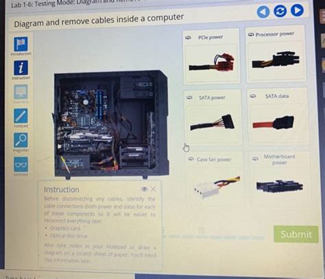
Table of Contents
Diagrams and Removing Cables Inside a Computer: A Comprehensive Guide
Opening up your computer case might seem daunting, but understanding the internal components and how to safely disconnect cables is crucial for upgrades, repairs, and even cleaning. This comprehensive guide provides a detailed walkthrough, complete with diagrams, to help you navigate the inner workings of your computer with confidence. We'll cover identifying components, safely disconnecting cables, and best practices for avoiding damage.
Understanding Your Computer's Interior: A Visual Guide
Before you even touch a cable, it's essential to understand the layout of your computer's components. This section provides a simplified overview, with visual aids to help you identify key parts. While specific layouts may vary slightly depending on the case and motherboard, the general principles remain the same.
Key Components and Their Locations:
-
Motherboard: The central hub of your computer, connecting all other components. It's usually the largest circuit board, often located near the bottom of the case. (Diagram: A simple diagram showing the motherboard's position and highlighting key connection points like CPU socket, RAM slots, expansion slots, etc.)
-
Central Processing Unit (CPU): The "brain" of your computer, responsible for processing instructions. It's typically a square chip mounted on the motherboard. (Diagram: Close-up diagram of the CPU showing the socket and heat sink.)
-
Random Access Memory (RAM): Short-term memory used by the computer to run applications. It's usually comprised of several small sticks that plug into slots on the motherboard. (Diagram: Diagram showing RAM sticks inserted into their slots on the motherboard.)
-
Graphics Processing Unit (GPU): Handles the rendering of images and video, often found on a separate card (graphics card) plugged into a PCIe slot on the motherboard. (Diagram: Diagram showing a graphics card inserted into a PCIe slot.)
-
Power Supply Unit (PSU): Provides power to all components. It's usually a large box located at the back of the case. (Diagram: Diagram showing the PSU location and its power connectors.)
-
Storage Drives (HDD/SSD): Store your data. These can be hard disk drives (HDDs) or solid-state drives (SSDs), typically mounted in bays within the case. (Diagram: Diagram illustrating different types of storage drive mounting – HDD and SSD.)
-
Case Fans: These help cool the components. They are typically mounted on the front, top, and/or back of the case. (Diagram: Diagram showing locations of typical case fans.)
Safely Disconnecting Cables: A Step-by-Step Approach
Now that you've identified the major components, let's focus on safely removing the cables. Remember, static electricity can damage sensitive components, so ground yourself before touching any internal parts. This can be done by touching a grounded metal object like the case (after turning off the computer and unplugging it).
1. Preparing Your Workspace:
- Turn off and unplug your computer. This is crucial to avoid electrical shocks and damage.
- Ground yourself. Touch a grounded metal object to discharge any static electricity.
- Create a clean workspace. A clean, well-lit area is essential to avoid accidental damage or misplaced components.
- Gather necessary tools. You might need a Phillips head screwdriver and potentially anti-static wrist strap.
2. Disconnecting Cables: A Detailed Guide
The process of disconnecting cables varies depending on the type of connection. Here's a breakdown of common cable types and removal techniques.
a) Power Cables:
- PSU to Motherboard: The 24-pin ATX power connector is the largest and most crucial. Gently but firmly push the release tab and pull the connector away from the motherboard. (Diagram: Close-up diagram showing the 24-pin ATX connector and its release mechanism.)
- CPU Power: The CPU power connector is usually a 4 or 8-pin connector. Locate the release tabs (if any) and gently disconnect it from the CPU. (Diagram: Close-up diagram showing the CPU power connector and its release mechanism.)
- Peripheral Power: SATA and Molex power connectors are used for storage drives and other peripherals. These usually have a simple latch. Gently press and pull to remove them. (Diagram: Close-up diagrams showing SATA and Molex connectors and their release mechanisms.)
b) Data Cables:
- SATA Data Cables: These connect storage drives to the motherboard. They typically have a latch mechanism. Gently press the latch and disconnect. (Diagram: Close-up diagram showing SATA data cable connection and disconnection.)
- Front Panel Connectors: These are typically located near the bottom of the motherboard and connect the case's front panel buttons, LEDs, and USB ports. Refer to your motherboard's manual for specific locations and connector pinouts. (Diagram: Diagram illustrating typical front panel connector locations and pinouts.)
c) Other Cables:
- GPU Power Cables: If your graphics card requires additional power, it will have 6-pin or 8-pin power connectors. These disconnect similarly to CPU power connectors. (Diagram: Close-up diagram showing a GPU power connector and its release mechanism.)
- Other Expansion Card Cables: If you have expansion cards like sound cards or network cards, they may have additional cables. Consult your card's documentation for instructions.
3. Cable Organization and Documentation:
- Take photos: Before disconnecting any cables, take clear photos of the cable routing. This helps immensely with reassembly.
- Label cables (optional): Use small labels to identify cables if needed. This is especially helpful for complex setups.
- Organize cables neatly: Keep cables organized and prevent tangling. This makes reassembly significantly easier.
Reassembling Your Computer: A Reverse Process
Once you've completed your work inside the computer case, carefully reassemble it, following the reverse steps of the disassembly process. Pay close attention to the following:
- Secure all cables: Ensure that all cables are firmly connected to their respective ports. Loose connections can cause malfunction.
- Proper cable routing: Route cables neatly and securely to avoid tangling and improve airflow.
- Double-check connections: Verify all connections before powering on your computer.
- Test your system: After reassembly, carefully power on your computer and test all components to ensure everything functions correctly.
Troubleshooting Common Issues
Even with careful attention to detail, you might encounter some problems. Here are some common issues and their possible solutions:
- Computer won't power on: Check all power connections, including the PSU switch, and ensure the power cord is securely connected.
- System boots but displays nothing: Verify that the monitor is properly connected and that the graphics card is seated correctly.
- System beeps repeatedly: This often indicates a hardware problem, such as missing or faulty RAM. Refer to your motherboard's manual for beep code interpretation.
- System instability (crashes or freezes): This could be due to loose connections, overheating, or driver issues.
Safety Precautions: Always Remember
- Always turn off and unplug your computer before working inside.
- Ground yourself to avoid static electricity damage.
- Work in a clean, well-lit area.
- Handle components carefully to avoid damage.
- Refer to your motherboard and component manuals for specific instructions.
By following this comprehensive guide and prioritizing safety, you can confidently navigate the interior of your computer, perform upgrades or repairs, and ensure the long-term health of your system. Remember, taking your time, being methodical, and referring to diagrams and manuals are keys to a successful experience.
Latest Posts
Latest Posts
-
How Should Students Prepare To Use Chemicals In The Lab
Mar 30, 2025
-
Which Are The Elements Of A System Of Care
Mar 30, 2025
-
A Challenge That Italy Faced After Unification Was
Mar 30, 2025
-
Why Is Myelin Important Check All That Apply
Mar 30, 2025
-
In Relation To The Wrist The Elbow Is
Mar 30, 2025
Related Post
Thank you for visiting our website which covers about Diagram And Remove Cables Inside A Computer . We hope the information provided has been useful to you. Feel free to contact us if you have any questions or need further assistance. See you next time and don't miss to bookmark.
