In A Dc Circuit What Limits Current Flow
Breaking News Today
Mar 25, 2025 · 6 min read
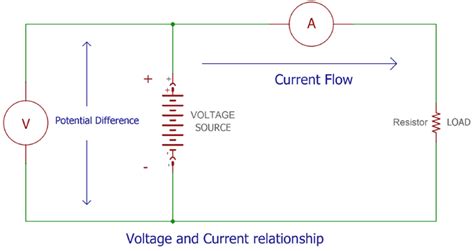
Table of Contents
In a DC Circuit, What Limits Current Flow?
Understanding what limits current flow in a direct current (DC) circuit is fundamental to electrical engineering and electronics. While Ohm's Law provides a simplified initial understanding (V=IR), the reality is far more nuanced. Several factors, individually and in combination, govern the precise amount of current that flows through a DC circuit. This article delves deep into these limitations, exploring both the theoretical and practical aspects.
Ohm's Law: The Foundation
Before exploring the complexities, let's revisit the cornerstone of DC circuit analysis: Ohm's Law. It states that the current (I) flowing through a conductor is directly proportional to the voltage (V) applied across it and inversely proportional to its resistance (R). Mathematically, this is represented as:
I = V/R
This seemingly simple equation is crucial, but it only tells part of the story. It assumes a purely resistive load and doesn't account for other factors that influence current flow in real-world circuits.
Beyond Ohm's Law: Factors Limiting Current Flow
While Ohm's Law provides a basic framework, several factors can significantly limit current flow in a DC circuit beyond simply the resistance of the load. These include:
1. Resistance: The Primary Limiting Factor
Resistance is the inherent opposition to the flow of current within a material. The higher the resistance, the lower the current for a given voltage. Resistance depends on several factors:
-
Material: Different materials possess different resistivity. Conductors like copper have low resistivity, while insulators like rubber have high resistivity.
-
Length: Longer conductors offer greater resistance. Imagine a longer, narrower pipe restricting water flow compared to a shorter, wider one.
-
Cross-sectional Area: A larger cross-sectional area allows for more current flow, reducing resistance. Think of a wider pipe allowing more water to pass.
-
Temperature: The resistance of most materials increases with increasing temperature. This is due to increased atomic vibrations hindering electron flow. Some materials, however, exhibit negative temperature coefficients, meaning their resistance decreases with increasing temperature.
2. Source Voltage: The Driving Force
The voltage source, whether a battery or a power supply, provides the electromotive force (EMF) that pushes electrons through the circuit. A higher voltage will drive more current, assuming the resistance remains constant. However, the source itself has internal resistance, limiting the maximum current it can deliver. This internal resistance is often represented as a small resistor in series with an ideal voltage source.
3. Internal Resistance of the Source: A Limiting Factor Within the Source
Every voltage source, be it a battery or a power supply, possesses some internal resistance. This resistance reduces the available voltage across the external circuit. As the current drawn from the source increases, the voltage drop across the internal resistance rises, reducing the voltage available to the load. This is often referred to as voltage sag or internal impedance.
Example: A 9V battery with an internal resistance of 1Ω connected to a 10Ω resistor will not deliver the full 9V to the resistor. The current will be lower than 9V/10Ω due to the voltage drop across the internal resistance of the battery.
4. Circuit Configuration: Series vs. Parallel
The way components are connected in a circuit significantly impacts the overall resistance and hence, the current.
-
Series Circuits: In series circuits, resistors add up directly (R<sub>total</sub> = R<sub>1</sub> + R<sub>2</sub> + ...). This increases the overall resistance, limiting the current.
-
Parallel Circuits: In parallel circuits, the reciprocal of the total resistance equals the sum of the reciprocals of individual resistances (1/R<sub>total</sub> = 1/R<sub>1</sub> + 1/R<sub>2</sub> + ...). This reduces the overall resistance, allowing for greater current flow, but each branch still experiences its own resistance-based current limitation.
5. Impedance in AC Circuits (Relevant for comparison):
While we're focusing on DC, it's important to note that in AC circuits, impedance plays a similar role to resistance. Impedance is a more general concept encompassing resistance, inductance, and capacitance. Inductors oppose changes in current, while capacitors oppose changes in voltage. Both significantly impact current flow in AC circuits.
6. Fuses and Circuit Breakers: Intentional Current Limiting
These safety devices are deliberately designed to limit current flow to prevent overloads and potential fires. Fuses melt and break the circuit when current exceeds a specific rating, while circuit breakers trip mechanically or electronically to interrupt the circuit. These devices are crucial for safety in electrical systems.
7. Saturable Reactors (Specialized Current Limiting):
In high-power DC applications, saturable reactors can be used to limit current. These devices have a magnetic core that saturates at a certain current level. Once saturation is reached, the reactor's inductance dramatically drops, limiting the further increase in current.
8. Transistors and Other Semiconductor Devices: Active Current Limiting
Transistors and other semiconductor devices can be used to actively control and limit current flow. They can act as electronically controlled switches or regulators, allowing for precise current control based on various parameters.
9. Thermal Effects and Power Dissipation: A Practical Limit
When current flows through a resistor, power is dissipated as heat (P = I²R). Excessive current leads to excessive heat generation. This heat can damage components, melt wires, or even cause fires. Therefore, the maximum allowable current is often limited by the thermal capacity of the components and wiring. Components have power ratings specifying the maximum power they can safely dissipate.
Calculating Current in Complex Circuits
Calculating current in more complex DC circuits involves applying Kirchhoff's laws. These laws provide a systematic approach to analyzing circuits with multiple loops and branches:
-
Kirchhoff's Current Law (KCL): The sum of currents entering a node (junction) is equal to the sum of currents leaving that node.
-
Kirchhoff's Voltage Law (KVL): The sum of voltage drops around any closed loop in a circuit is equal to zero.
Using these laws, along with Ohm's Law, allows for the calculation of currents flowing through individual components and branches in complex circuits. Techniques like nodal analysis and mesh analysis are employed for solving large and complex circuit networks.
Practical Applications and Considerations
The concepts discussed above are crucial for numerous applications:
-
Power Supply Design: Power supply designers need to ensure that the power supply can deliver sufficient current to the load without exceeding its limits or causing damage.
-
Motor Control: Controlling the speed and torque of DC motors often involves regulating the current supplied to the motor.
-
Battery Management Systems (BMS): BMS in electric vehicles and other battery-powered systems monitor and control the current flow to and from the battery, protecting it from overcharging and over-discharging.
-
Protection Circuits: Fuses, circuit breakers, and other protection devices prevent damage to circuits and equipment due to overcurrent conditions.
Conclusion
Understanding what limits current flow in a DC circuit extends far beyond a simple application of Ohm's Law. Numerous factors, interacting in complex ways, determine the precise current value. A thorough understanding of these factors – resistance, voltage source characteristics, circuit configuration, safety devices, and thermal considerations – is crucial for designing, troubleshooting, and maintaining safe and efficient DC circuits. This knowledge is fundamental to a successful career in electrical engineering, electronics, and related fields. Successfully navigating these complexities will equip you to analyze, design, and troubleshoot real-world DC circuits confidently and effectively.
Latest Posts
Latest Posts
Related Post
Thank you for visiting our website which covers about In A Dc Circuit What Limits Current Flow . We hope the information provided has been useful to you. Feel free to contact us if you have any questions or need further assistance. See you next time and don't miss to bookmark.
